Introduction & Use Case
🕸️ Every October, the soldering irons come out ⚡, the LEDs start to flicker🚨, and I find myself knee-deep in code👨💻, hot glue🧴, and pumpkin guts🎃. It’s tradition at this point — a blend of maker-mayhem and mild madness that turns my workshop into something between a tech lab and Frankenstein’s garage.
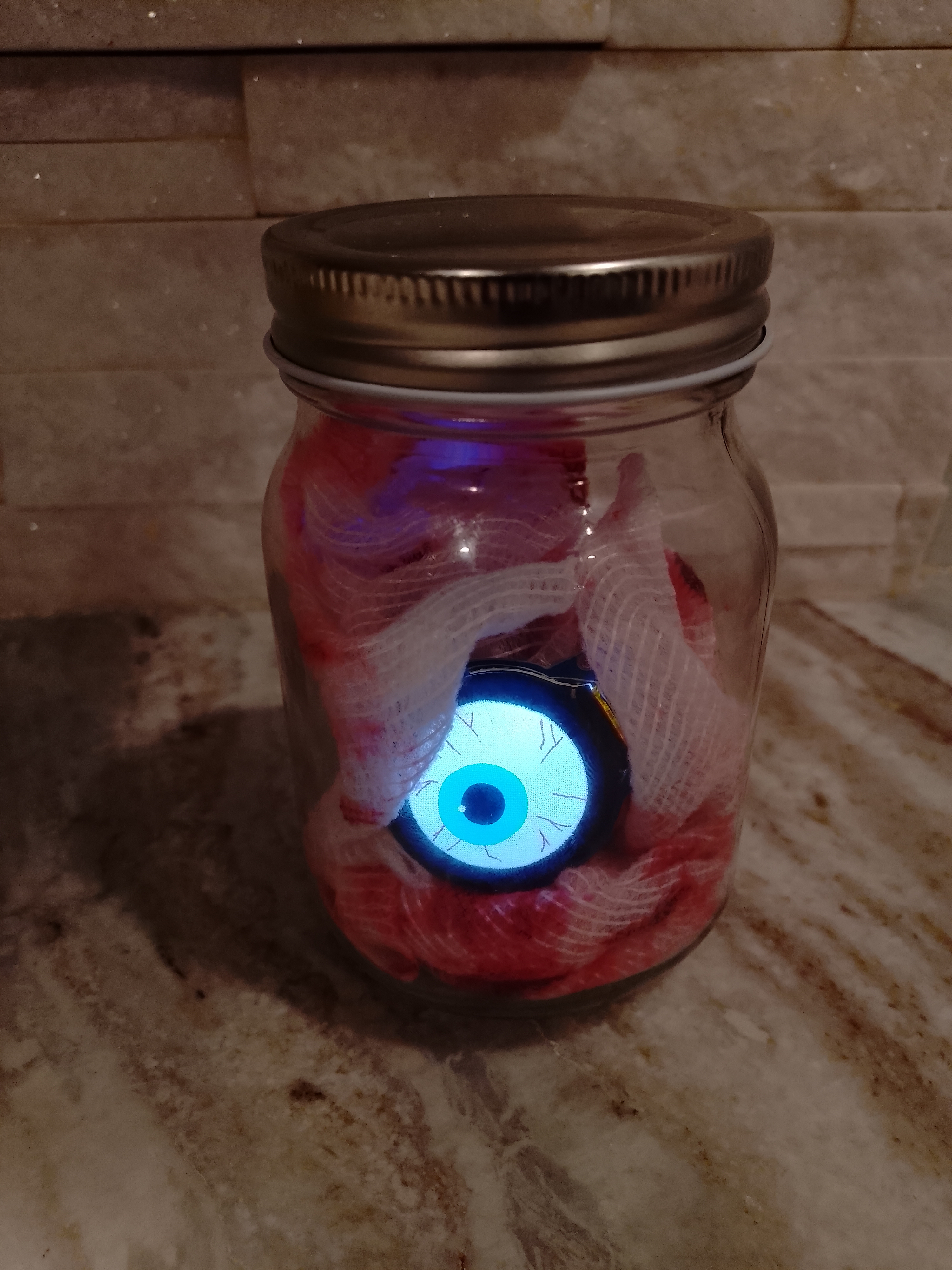
This year, the madness spilled into the SOC — where a watchful Eye of Sauron now surveys dashboards and detections 👁️🔥. Nothing says “security awareness month” like deploying a flaming, all-seeing sentinel to keep your analysts on their toes.
So fire up your Pi, cue up your synthwave playlist, and let’s raise a few spirits — digitally, of course. 👻
In This Post We Will
Part 1 — Build the GC9A01 Eye
- 🔌 Set up a headless Raspberry Pi (Bookworm Lite 32-bit, SSH).
- 🧪 Enable SPI and install required packages (Pillow, NumPy, spidev).
- 🛠️ Create the project folder and build a GC9A01 driver (SPI + RGB565).
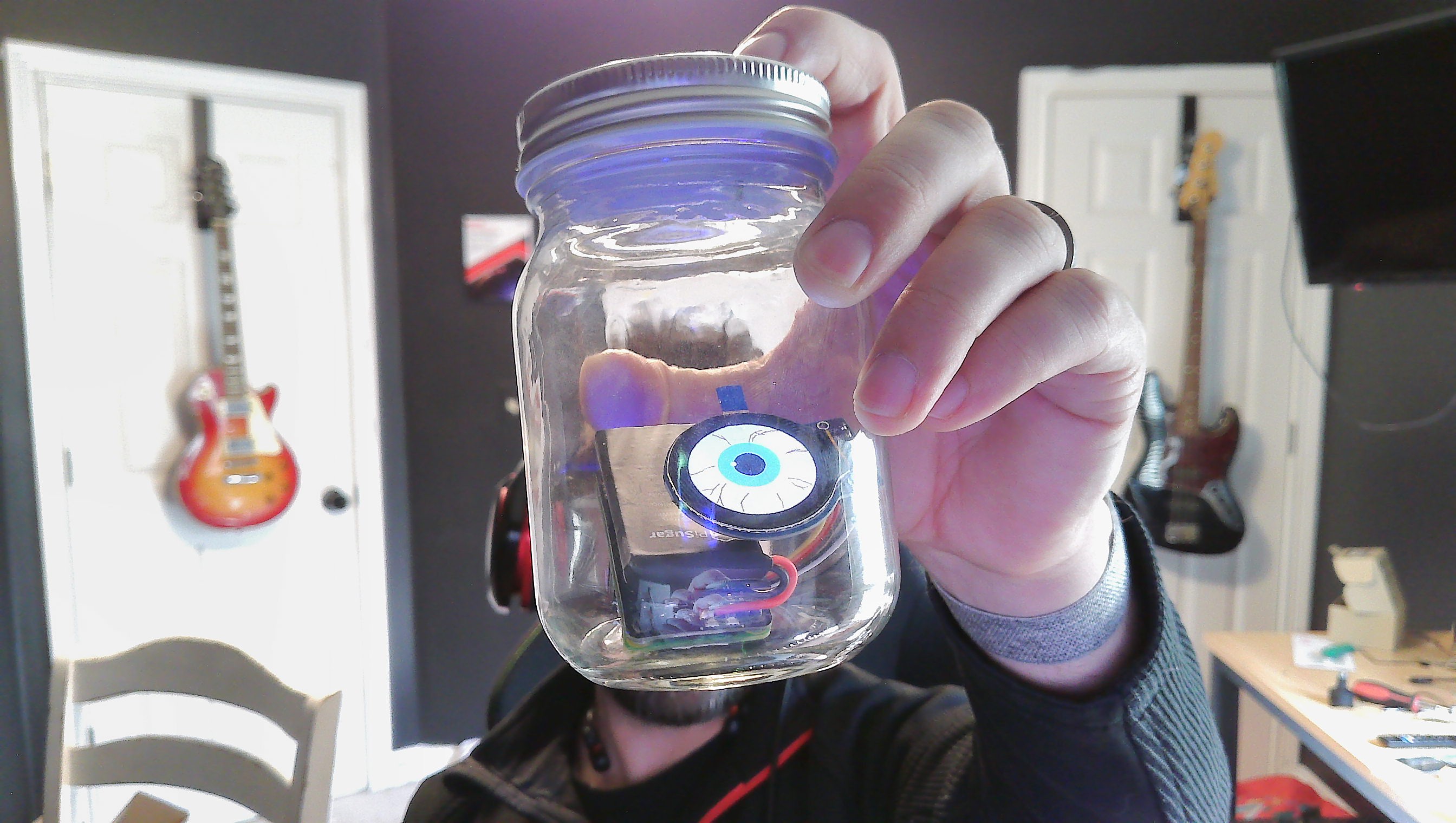
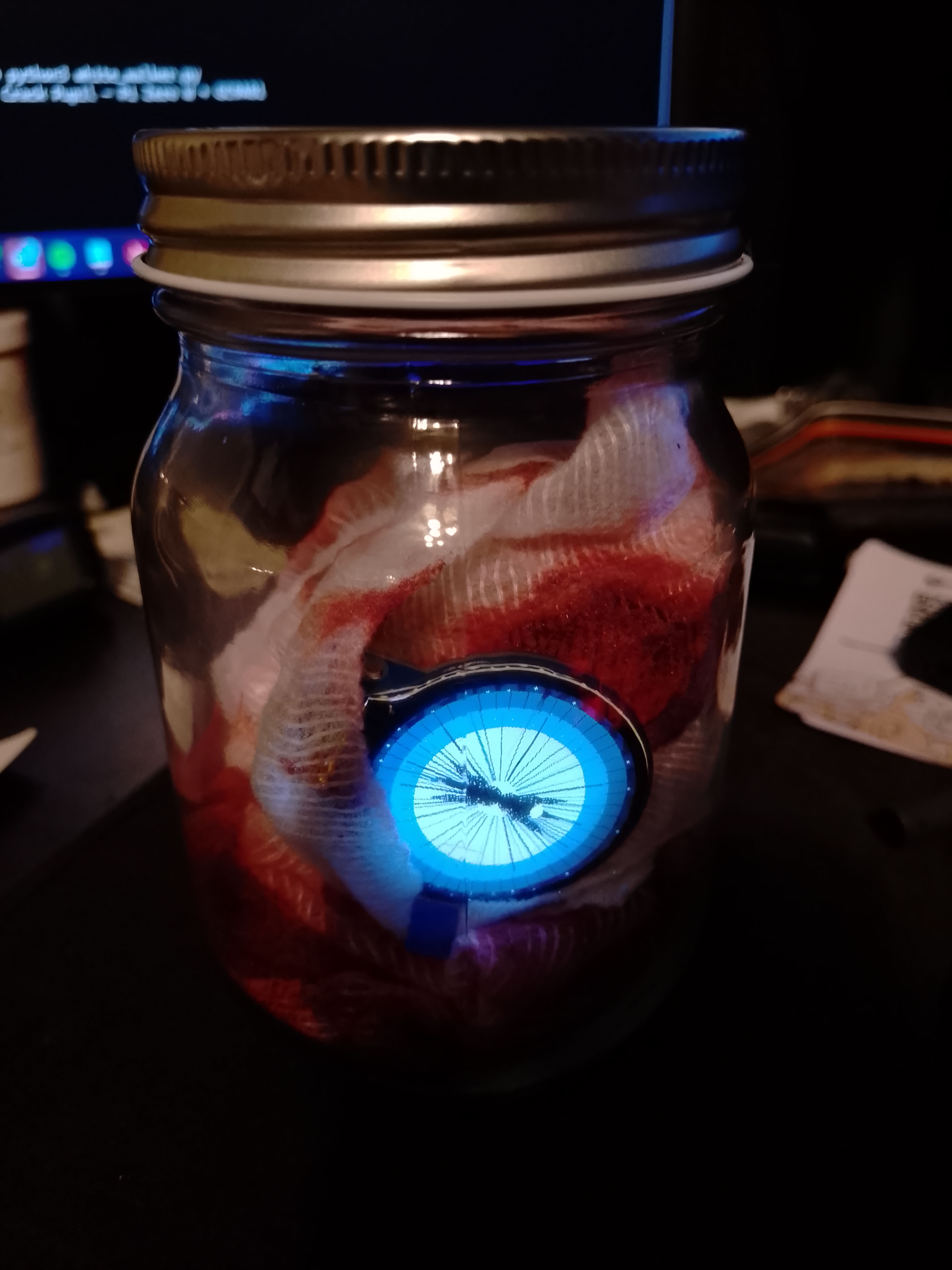
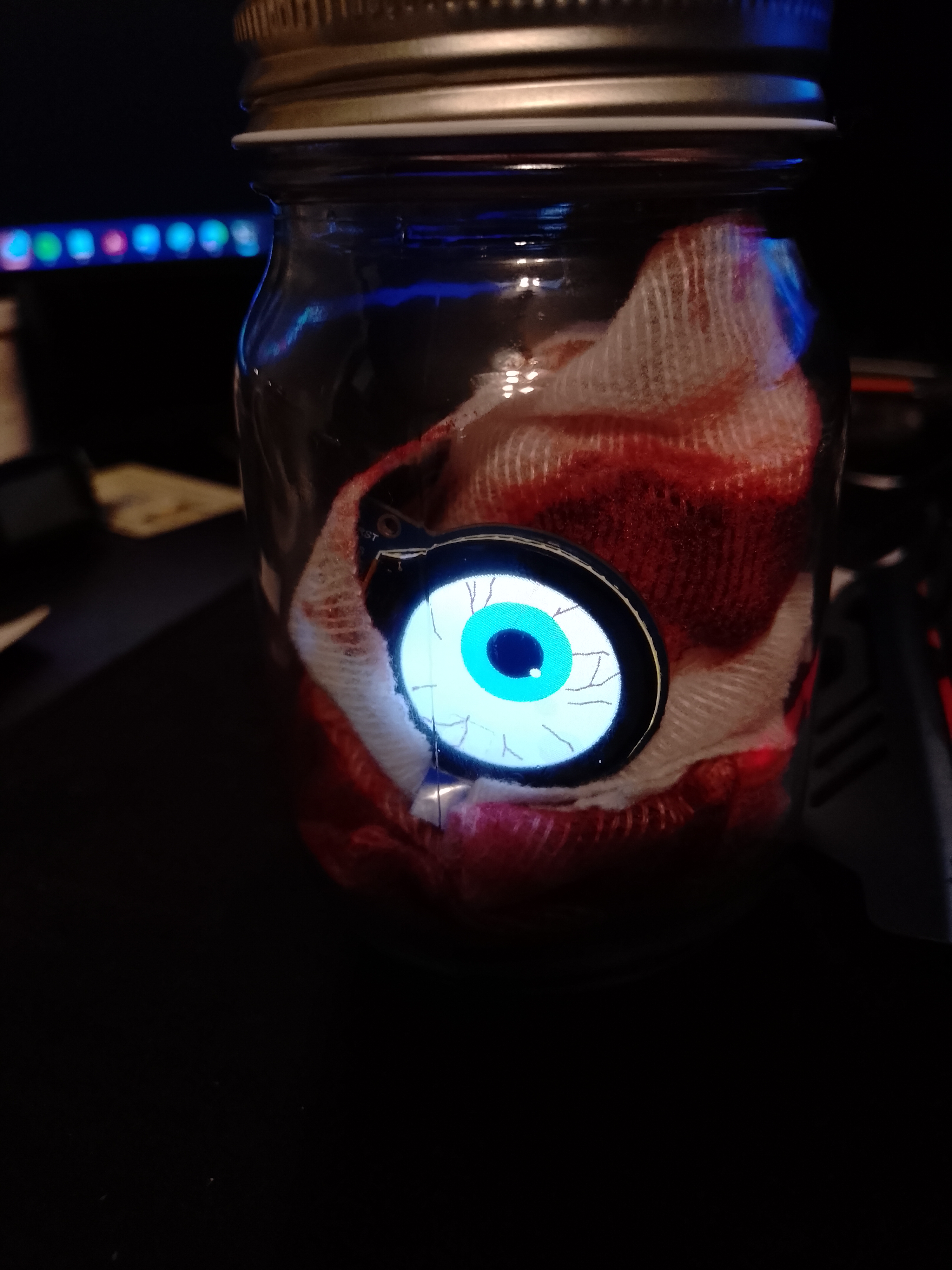
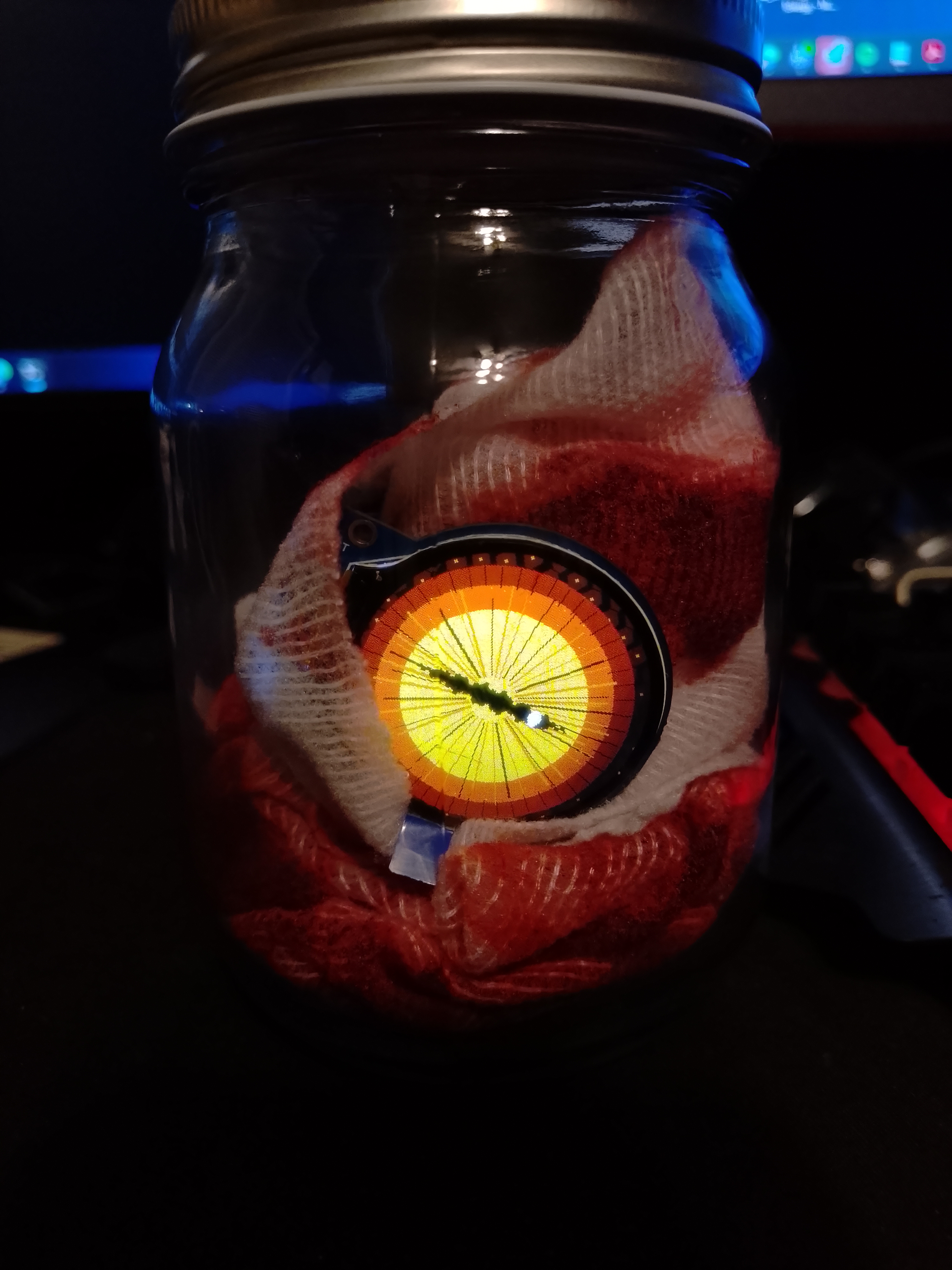
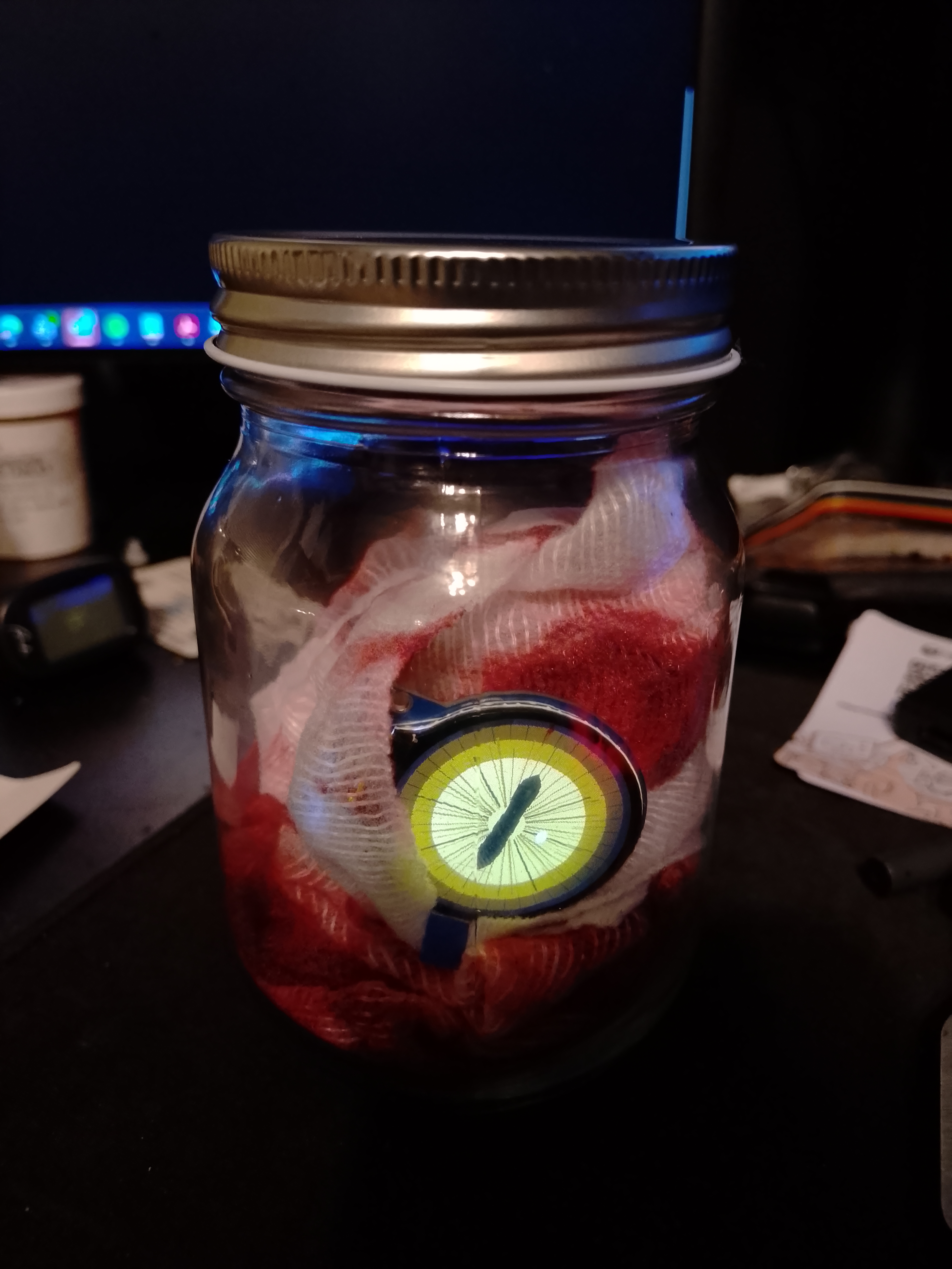
- 👁️ Run animated “eyeball-in-a-jar” scripts and swap eye templates (Goat, Dragon, White-Walker).
Part 2 — Deploy, Customize & Optimize
- ⚙️ Auto-start on boot with systemd (create, enable, manage eyeball.service).
- 🕹️ Use control commands & logs to start/stop/restart and troubleshoot.
- 🎨 Customize colors/iris effects and switch between eye scripts quickly.
- 🩺 Diagnose display issues with single-color and quadrant tests; apply full init & gamma.
- 🚀 Optimize FPS using NumPy vectorization, chunked SPI writes, and higher SPI clock (≈6× boost).
Hardware Prerequisites
- Raspberry Pi board (tested on Pi3ModelB+, PiZeroWH, and PiZero2WH)
- GC9A01 1.28” round display
- Pisugar S Portable 1200 mAh UPS Lithium Battery Pwnagotchi Power Module Power Supply
- Breadboard Jumper Wires (female on both ends)
- Mason Jar
Perform a Headless Raspberry Pi Setup (BookwormOS)
1. Grab the OS image from the official Raspberry Pi site (don’t extract, leave it as is).
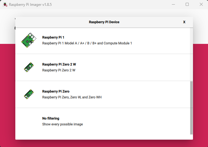
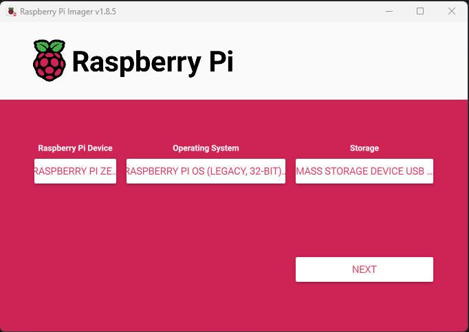
2. Insert your SD card into the reader and run the Raspberry Pi Imager (available here).
![]()
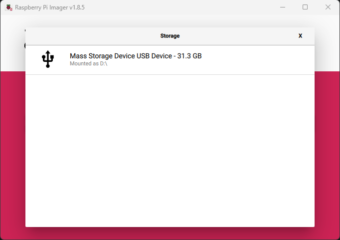
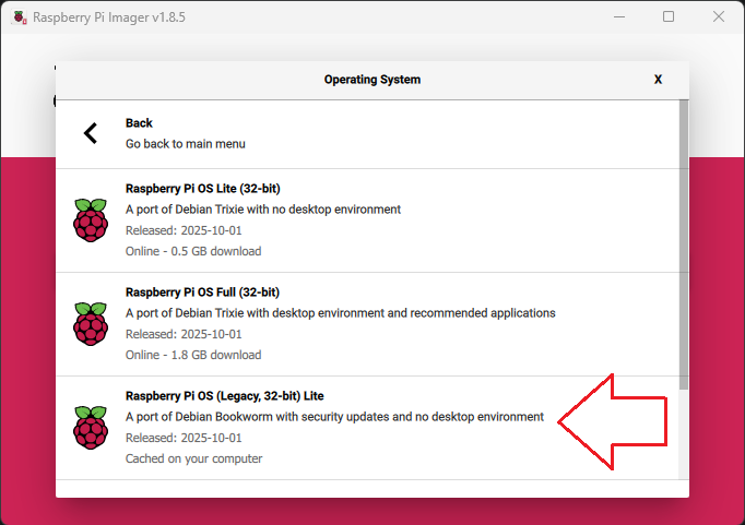
3. Select your hardware, desired OS, and destination storage (SD Card) as illustrated below…
💡 IMPORTANT –> Make sure you grab the legacy 32bit Bookworm Lite OS with Security Updates and no desktop; as this software is not supported as-is on the latest Bookworm OS 👇
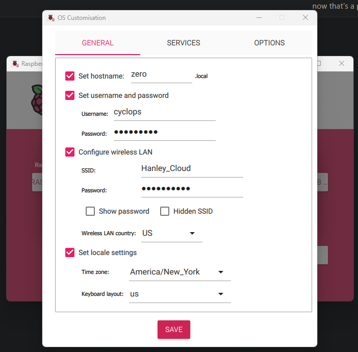
4. Select Next and you will be prompted with the option to edit OS settings. Select Edit and enter your network SSID and PSK, as well as your desired username and password.
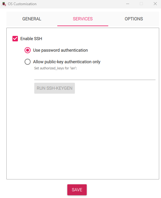
5. Navigate from the General tab over to the SSH tab and make sure it’s enabled with password authentication as shown below…
6. Click Next and let it burn! 🔥

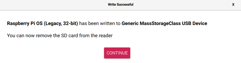
7. Drop the SD card into your Raspberry Pi board and boot it up.
8. Locate it on the network (login to your router or use Advanced IP Scanner) and SSH into it.
PHASE 1: Enable SPI
# Enable SPI interface
sudo raspi-config
Navigate to:
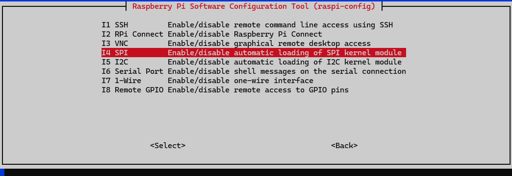
- Select 3 Interface Options
- Select I4 SPI
- Select Yes
- Select Finish
- Select Yes to reboot
After reboot, verify SPI is enabled:
ls /dev/spidev*
Should show: /dev/spidev0.0  /dev/spidev0.1  # <-- Look for both 0.0 and 0.1
PHASE 2: Install Dependencies
# Update system
sudo apt-get update && sudo apt-get upgrade -y

# Install required packages
sudo apt-get install -y python3-pip python3-pil python3-numpy

# Install Python SPI library
sudo pip3 install spidev --break-system-packages
PHASE 3: Create Project Directory
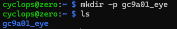
# Create directory
cd ~
mkdir -p gc9a01_eye
cd gc9a01_eye
PHASE 4: Build our GC9A01 Display Driver
sudo nano gc9a01_driver.py
Paste this complete driver code:
#!/usr/bin/env python3
"""
GC9A01 Display Driver for Raspberry Pi
1.28" Round LCD Display (240x240 pixels)
Communicates via SPI with RGB565 color format
"""

import RPi.GPIO as GPIO  # For controlling GPIO pins (DC and RST)
import spidev            # For SPI communication with the display
import time              # For delays during initialization
import numpy as np       # For fast image processing and RGB565 conversion

# Pin definitions (BCM numbering)
DC = 24   # Data/Command pin - tells display if we're sending a command or data
RST = 25  # Reset pin - used to hardware reset the display

class GC9A01:
    """
    Driver class for GC9A01 round LCD display
    Handles initialization, communication, and image rendering
    """

    def __init__(self):
        """
        Initialize GPIO pins and SPI connection
        Sets up the hardware interface to the display
        """
        self.width = 240   # Display width in pixels
        self.height = 240  # Display height in pixels

        # Configure GPIO pins
        GPIO.setmode(GPIO.BCM)      # Use BCM pin numbering (GPIO numbers, not physical pins)
        GPIO.setwarnings(False)     # Disable warnings if pins already in use
        GPIO.setup(DC, GPIO.OUT)    # Set DC pin as output (we control it)
        GPIO.setup(RST, GPIO.OUT)   # Set RST pin as output (we control it)

        # Configure SPI (Serial Peripheral Interface)
        self.spi = spidev.SpiDev()
        self.spi.open(0, 0)  # Open SPI bus 0, device (CS) 0
        # Set SPI clock speed to 60MHz for fast data transfer
        # This determines how quickly we can push pixels to the display
        self.spi.max_speed_hz = 60000000

    def cmd(self, c, *data):
        """
        Send a command to the display, optionally followed by data bytes

        Args:
            c: Command byte (e.g., 0x11 for sleep out)
            *data: Optional data bytes to send after the command

        How it works:
        - DC pin LOW = sending a command
        - DC pin HIGH = sending data
        This is how the display knows whether we're telling it WHAT to do (command)
        or WHAT to display/configure (data)
        """

        GPIO.output(DC, GPIO.LOW)   # Pull DC LOW to indicate command mode
        self.spi.writebytes([c])    # Send the command byte via SPI

        if data:  # If there are data bytes to send
            GPIO.output(DC, GPIO.HIGH)      # Pull DC HIGH to indicate data mode
            self.spi.writebytes(list(data)) # Send the data bytes

    def reset(self):
        """
        Perform hardware reset of the display

        The reset sequence:
        1. Pull RST LOW for 100ms (puts display in reset state)
        2. Pull RST HIGH (releases reset)
        3. Wait 120ms for display to fully initialize

        This is like pressing the reset button - clears all settings
        """
        GPIO.output(RST, GPIO.LOW)   # Assert reset (active low)
        time.sleep(0.1)              # Hold reset for 100ms
        GPIO.output(RST, GPIO.HIGH)  # Release reset
        time.sleep(0.12)             # Wait for display to boot up

    def init(self):
        """
        Initialize the GC9A01 display with full configuration

        This method sends dozens of commands to configure:
        - Power settings
        - Display orientation
        - Color format (RGB565)
        - Gamma correction (for accurate colors)
        - Timing parameters

        The GC9A01 has many internal registers that control how it displays images.
        These commands set up optimal settings for our use case.
        """
        self.reset()  # Start with a clean slate

        # === Inter Register Enable Commands ===
        # These unlock hidden/advanced registers for configuration
        self.cmd(0xEF)           # Inter register enable 1
        self.cmd(0xEB, 0x14)     # Inter register enable 2

        self.cmd(0xFE)           # Inter register enable 1 (again)
        self.cmd(0xEF)           # Inter register enable 1 (again)

        self.cmd(0xEB, 0x14)     # Inter register enable 2 (again)

        # === Power Control Registers ===
        # These control voltage levels and power management
        self.cmd(0x84, 0x40)     # Power control 1
        self.cmd(0x85, 0xFF)     # Power control 2
        self.cmd(0x86, 0xFF)     # Power control 3
        self.cmd(0x87, 0xFF)     # Power control 4
        self.cmd(0x88, 0x0A)     # Power control 5
        self.cmd(0x89, 0x21)     # Power control 6
        self.cmd(0x8A, 0x00)     # Power control 7
        self.cmd(0x8B, 0x80)     # Power control 8
        self.cmd(0x8C, 0x01)     # Power control 9
        self.cmd(0x8D, 0x01)     # Power control 10
        self.cmd(0x8E, 0xFF)     # Power control 11
        self.cmd(0x8F, 0xFF)     # Power control 12

        # === Display Function Control ===
        # 0xB6: Controls display scanning direction and timing
        # Parameters: [0x00, 0x20] sets normal scan direction
        self.cmd(0xB6, 0x00, 0x20)

        # === Memory Access Control (MADCTL) ===
        # 0x36: Controls how memory is written (orientation, color order)
        # 0x48 means:
        #   - RGB color order (not BGR)
        #   - Normal horizontal and vertical refresh
        #   - Row/column address order for proper orientation
        self.cmd(0x36, 0x48)

        # === Pixel Format ===
        # 0x3A: Sets the color format for RGB interface
        # 0x05 = 16-bit RGB565 format
        #   - 5 bits red, 6 bits green, 5 bits blue
        #   - Total: 16 bits (2 bytes) per pixel
        #   - 65,536 possible colors
        self.cmd(0x3A, 0x05)

        # === Frame Rate Control ===
        # Controls how fast the display refreshes
        self.cmd(0x90, 0x08, 0x08, 0x08, 0x08)

        # === Display Inversion Control ===
        self.cmd(0xBD, 0x06)     # Display inversion control
        self.cmd(0xBC, 0x00)     # Display inversion control 2

        # === More Power/Voltage Settings ===
        self.cmd(0xFF, 0x60, 0x01, 0x04)  # Vreg1a/Vreg1b voltage
        self.cmd(0xC3, 0x13)               # Vreg1a voltage
        self.cmd(0xC4, 0x13)               # Vreg1b voltage
        self.cmd(0xC9, 0x22)               # Vreg2a voltage

        self.cmd(0xBE, 0x11)     # Frame rate control in normal mode

        self.cmd(0xE1, 0x10, 0x0E)  # Set equalize time

        self.cmd(0xDF, 0x21, 0x0C, 0x02)  # Set gate timing

        # === GAMMA CORRECTION ===
        # Gamma correction ensures colors look natural and accurate
        # Without it, colors would look washed out or incorrect
        # These are carefully tuned values for the GC9A01

        # Positive Voltage Gamma Control
        # Controls how colors appear in bright areas
        self.cmd(0xF0, 0x45, 0x09, 0x08, 0x08, 0x26, 0x2A)

        # Negative Voltage Gamma Control
        # Controls how colors appear in dark areas
        self.cmd(0xF1, 0x43, 0x70, 0x72, 0x36, 0x37, 0x6F)

        # Positive Voltage Gamma Control (second set)
        self.cmd(0xF2, 0x45, 0x09, 0x08, 0x08, 0x26, 0x2A)

        # Negative Voltage Gamma Control (second set)
        self.cmd(0xF3, 0x43, 0x70, 0x72, 0x36, 0x37, 0x6F)

        # === Additional Display Settings ===
        self.cmd(0xED, 0x1B, 0x0B)  # Power control
        self.cmd(0xAE, 0x77)        # Unknown register
        self.cmd(0xCD, 0x63)        # Unknown register

        # Digital Gamma Control - fine-tunes gamma curves
        self.cmd(0x70, 0x07, 0x07, 0x04, 0x0E, 0x0F, 0x09, 0x07, 0x08, 0x03)

        self.cmd(0xE8, 0x34)  # Frame rate control

        # === Gate Control ===
        # These registers control the gate driver (row scanning)
        self.cmd(0x62, 0x18, 0x0D, 0x71, 0xED, 0x70, 0x70,
                      0x18, 0x0F, 0x71, 0xEF, 0x70, 0x70)

        self.cmd(0x63, 0x18, 0x11, 0x71, 0xF1, 0x70, 0x70,
                      0x18, 0x13, 0x71, 0xF3, 0x70, 0x70)

        self.cmd(0x64, 0x28, 0x29, 0xF1, 0x01, 0xF1, 0x00, 0x07)

        # === Source Control ===
        # These control the source driver (column scanning)
        self.cmd(0x66, 0x3C, 0x00, 0xCD, 0x67, 0x45, 0x45,
                      0x10, 0x00, 0x00, 0x00)

        self.cmd(0x67, 0x00, 0x3C, 0x00, 0x00, 0x00, 0x01,
                      0x54, 0x10, 0x32, 0x98)

        self.cmd(0x74, 0x10, 0x85, 0x80, 0x00, 0x00, 0x4E, 0x00)

        self.cmd(0x98, 0x3E, 0x07)  # Unknown register

        # === Tearing Effect Line ===
        # 0x35: Enable tearing effect signal
        # Helps synchronize with the display refresh to prevent tearing
        self.cmd(0x35)

        # === Display Inversion ===
        # 0x21: Turn ON display inversion
        # Some GC9A01 displays need this for correct colors
        # If colors look wrong, try 0x20 (inversion OFF) instead
        self.cmd(0x21)

        # === Sleep Out ===
        # 0x11: Exit sleep mode
        # The display starts in sleep mode after reset
        # This wakes it up so it can display images
        self.cmd(0x11)
        time.sleep(0.12)  # Wait 120ms for display to wake up (required by datasheet)

        # === Display ON ===
        # 0x29: Turn on the display
        # After this command, the display will show whatever is in its memory
        self.cmd(0x29)
        time.sleep(0.02)  # Brief delay to ensure display is fully on

    def show_numpy(self, image):
        """
        Display a PIL Image on the screen using optimized numpy conversion

        This is the fastest way to send images to the display.

        Process:
        1. Convert PIL image to numpy array
        2. Extract R, G, B channels
        3. Convert RGB888 (24-bit) to RGB565 (16-bit)
        4. Pack into byte array
        5. Send to display via SPI

        Args:
            image: PIL Image object (240x240 pixels)
        """
        # Convert PIL image to numpy array
        # This gives us a 3D array: [height, width, 3]
        # where the 3 channels are R, G, B values (0-255 each)
        img_array = np.array(image.convert('RGB'))

        # Extract individual color channels and convert to 16-bit for math
        r = img_array[:, :, 0].astype(np.uint16)  # Red channel
        g = img_array[:, :, 1].astype(np.uint16)  # Green channel
        b = img_array[:, :, 2].astype(np.uint16)  # Blue channel

        # === RGB565 CONVERSION ===
        # RGB888 (24-bit): 8 bits per channel = 16.7 million colors
        # RGB565 (16-bit): 5 red, 6 green, 5 blue = 65,536 colors
        #
        # Why 6 bits for green? Human eyes are most sensitive to green!
        #
        # Conversion formula:
        # - Red:   Take top 5 bits (& 0xF8), shift left 8 positions
        # - Green: Take top 6 bits (& 0xFC), shift left 3 positions
        # - Blue:  Take top 5 bits (>> 3), no shift needed
        #
        # Example: RGB(255, 128, 64) becomes:
        # Red:   11111000 << 8  = 1111100000000000
        # Green: 10000000 << 3  = 0000001000000000
        # Blue:  01000000 >> 3  = 0000000000001000
        # Result: 1111101000001000 (0xFA08)
        rgb565 = ((r & 0xF8) << 8) | ((g & 0xFC) << 3) | (b >> 3)

        # Split 16-bit values into high and low bytes
        # SPI sends 8 bits at a time, so we need to split each pixel
        # into 2 bytes: high byte first, then low byte
        high = (rgb565 >> 8).astype(np.uint8)   # Top 8 bits
        low = (rgb565 & 0xFF).astype(np.uint8)  # Bottom 8 bits

        # Interleave high and low bytes
        # Display expects: [high1, low1, high2, low2, high3, low3, ...]
        # We create a 3D array: [height, width, 2] where 2 = [high, low]
        buf = np.empty((self.height, self.width, 2), dtype=np.uint8)
        buf[:, :, 0] = high  # First byte of each pixel
        buf[:, :, 1] = low   # Second byte of each pixel

        # Flatten to 1D array for SPI transmission
        # Converts [240, 240, 2] array into [115,200] byte array
        # (240 * 240 pixels * 2 bytes per pixel = 115,200 bytes)
        data = buf.flatten().tolist()

        # === SET DRAWING WINDOW ===
        # Tell the display which area of the screen to update
        # We're updating the entire screen (0,0 to 239,239)

        # 0x2A: Column Address Set
        # Parameters: [start_high, start_low, end_high, end_low]
        # We're setting columns 0 to 239 (0x00EF)
        self.cmd(0x2A, 0, 0, 0, 239)

        # 0x2B: Row Address Set
        # Parameters: [start_high, start_low, end_high, end_low]
        # We're setting rows 0 to 239 (0x00EF)
        self.cmd(0x2B, 0, 0, 0, 239)

        # 0x2C: Memory Write
        # After this command, all following data goes to display memory
        self.cmd(0x2C)

        # === SEND PIXEL DATA ===
        # Switch DC pin HIGH to send data (not commands)
        GPIO.output(DC, GPIO.HIGH)

        # Send data in 4KB chunks for efficiency
        # Sending all 115,200 bytes at once could cause issues
        # Chunking reduces memory usage and improves reliability
        chunk_size = 4096  # 4KB chunks
        for i in range(0, len(data), chunk_size):
            # Send one chunk at a time
            self.spi.writebytes(data[i:i+chunk_size])

    def cleanup(self):
        """
        Clean up GPIO and SPI resources

        IMPORTANT: Always call this when you're done!
        Releases the SPI bus and resets GPIO pins
        Failure to call this can cause issues with other programs
        """
        self.spi.close()    # Close SPI connection
        GPIO.cleanup()      # Reset all GPIO pins to default state
Save with Ctrl+X, Y, Enter.
PHASE 5: Create Eye Scripts
Copy and paste the different python powered eyeballs from my Github page into the working folder on your Raspberry Pi.
PHASE 7: Set Up Auto-Start on Boot
””” Note which eye you want to run on boot, then: “””
# Create systemd service
sudo nano /etc/systemd/system/eyeball.service
…and paste the following:
ini[Unit]
Description=GC9A01 Eyeball Display
After=multi-user.target

[Service]
Type=simple
User=cyclops
WorkingDirectory=/home/cyclops/gc9a01_eye
ExecStart=/usr/bin/python3 /home/cyclops/gc9a01_eye/bloodshot.py # <-- ⚠️ Change ThisGuy.py to your preferred eye animation 👀
Restart=on-failure
RestartSec=10

[Install]
WantedBy=multi-user.target
Save with Ctrl+X, Y, Enter, then enable auto-start:
# Reload systemd
sudo systemctl daemon-reload
Enable service to start on boot
sudo systemctl enable eyeball.service
Start it now (test without rebooting)
sudo systemctl start eyeball.service
Check status
sudo systemctl status eyeball.service
Should show: Active: active (running)
Test by rebooting:
sudo reboot -h now
Wait 30-60 seconds after boot, and the eye should start automatically!
PHASE 8: Control Commands (Reference)
# Stop the eye
sudo systemctl stop eyeball.service

# Start the eye
sudo systemctl start eyeball.service

# Restart the eye (after making changes)
sudo systemctl restart eyeball.service

# Disable auto-start on boot
sudo systemctl disable eyeball.service

# View live logs
sudo journalctl -u eyeball.service -f

# View last 50 log lines
sudo journalctl -u eyeball.service -n 50
Customization Tips
Change Eye Colors
sudo nano ~/gc9a01_eye/eyeball.py
Find these lines near the top and modify:
# Make it more orange/red
IRIS_COLOR = (255, 100, 0)
FLAME_INNER = (255, 150, 0)

# Make it green
IRIS_COLOR = (100, 255, 100)
FLAME_INNER = (150, 255, 100)

#After changing, restart:
sudo systemctl restart eye.service
Switch to Different Eye
# Edit service file
sudo nano /etc/systemd/system/eye.service

# Change the ExecStart line to:
ExecStart=/usr/bin/python3 /home/cyclops/gc9a01_eye/bloodshot.py

# Reload and restart
sudo systemctl daemon-reload
sudo systemctl restart eye.service
Quick Troubleshooting
Eye doesn’t start on boot:
sudo systemctl status eye.service
sudo journalctl -u eye.service -n 50
Display shows nothing:
# Check wiring & Verify SPI is enabled
ls /dev/spidev*
Low FPS:
# Check CPU temperature
vcgencmd measure_temp
If overheating/Need to stop it quickly:
sudo systemctl stop eye.service
File Structure Summary
After setup, you’ll have:
/home/usr/gc9a01_eye/
├── gc9a01_driver.py          # Display driver
├── fire_dragon.py            # Fiery dragon eye
├── bloodshot_eye.py          # Bloodshot eye
└── ...                         ...

/etc/systemd/system/
└── eye.service              # Auto-start service
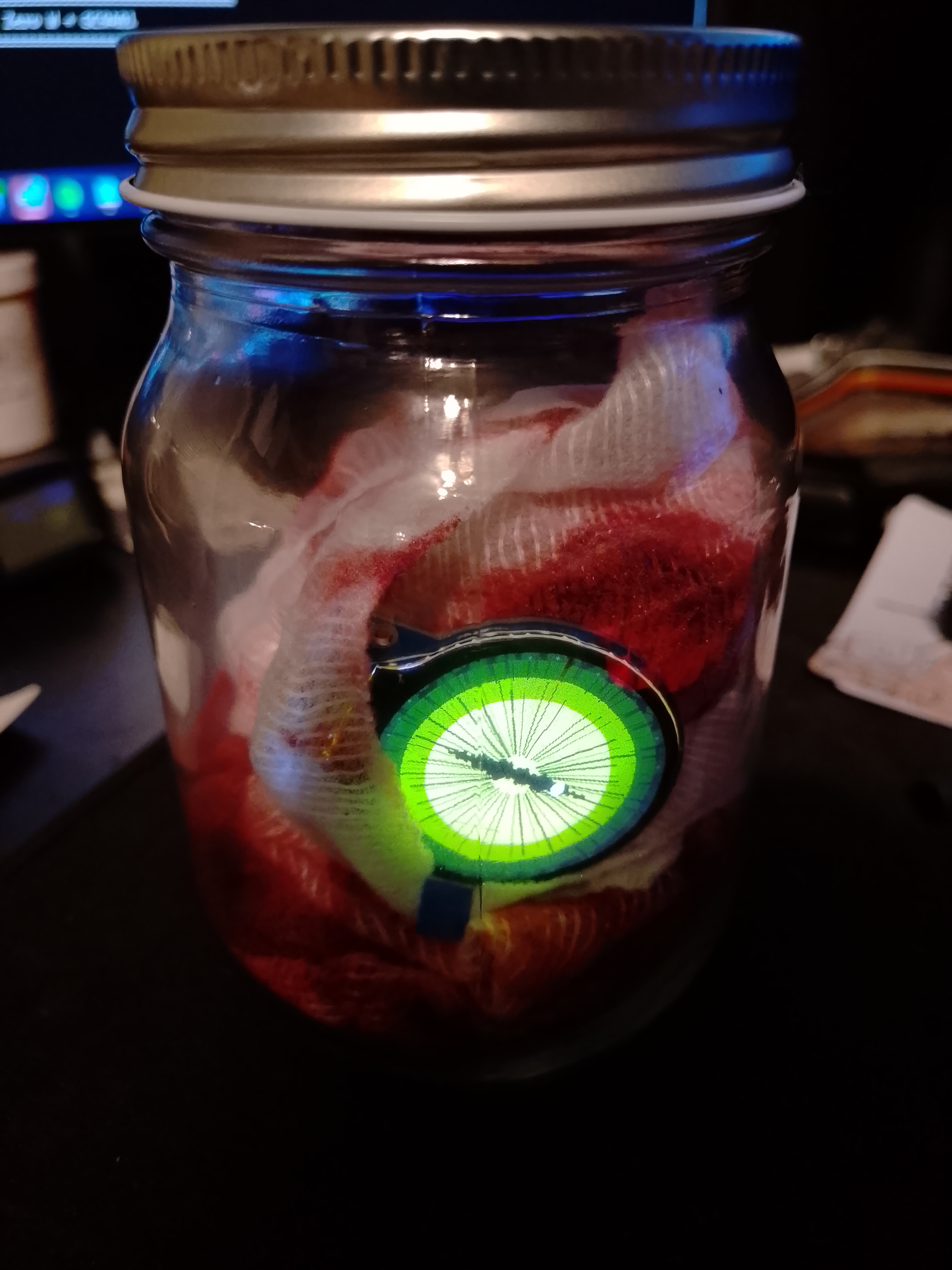
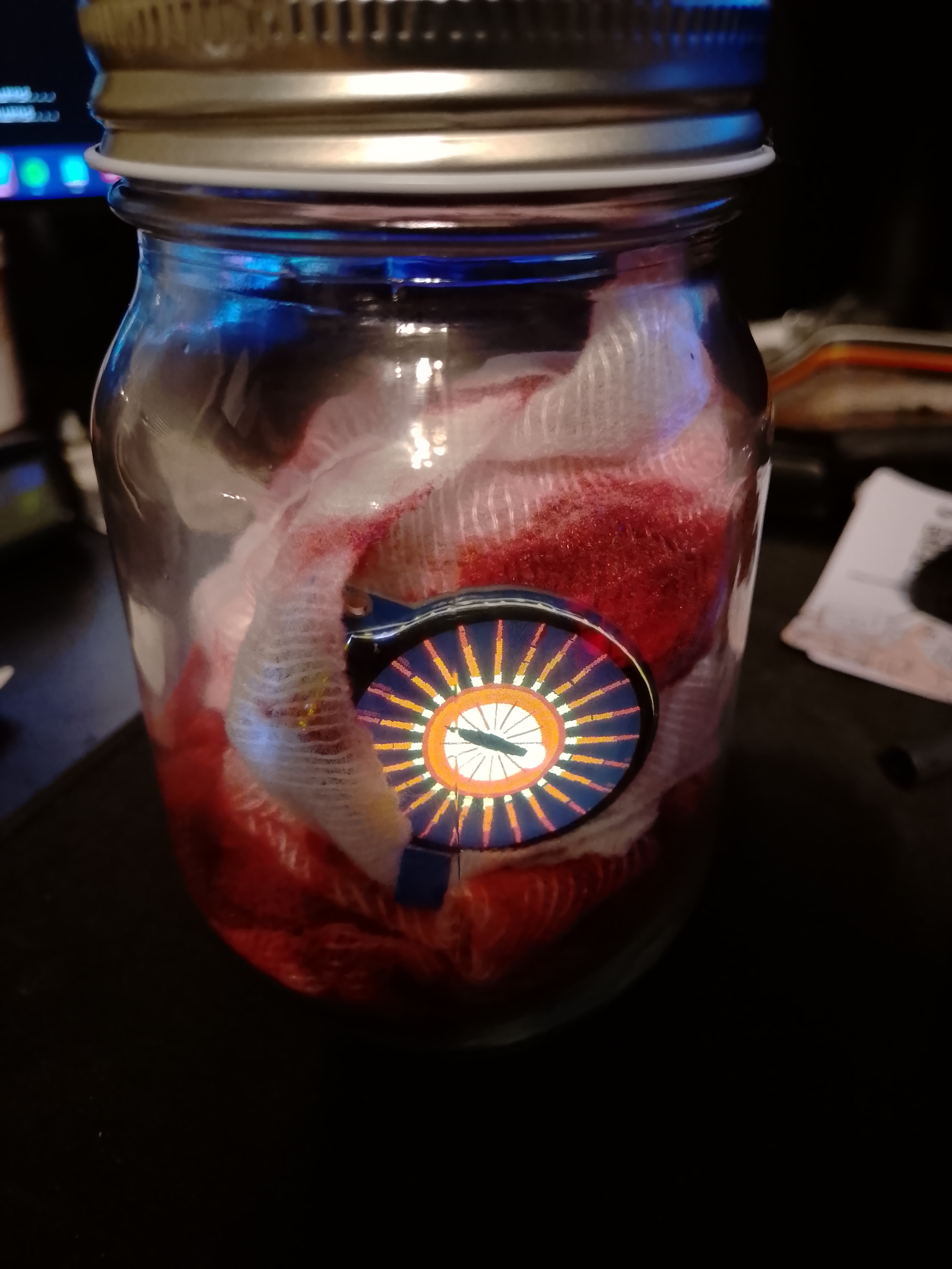
The Finishing Touches
For our Pièce de Résistance, apply some fake blood to some medical grade gauss and let it dry. Next we can stuff some in the bottom of the jar, wrap the raspberry pi and voilà!
Degubbing the Display Voltage and Optimizing the Driver for Maximum FPS
At first the display would not behave. My first attempt to draw basic PIL circles didn’t look right. It took some trial and error to rule out a hardware or soldering fault. At first it would flicker on boot, and the colours with very dark and blurred, with some shapes failing to draw outright.
The Breakthrough: The Colour Test
I created a simple test that filled the entire screen with different solid colors in sequence:
# Test each color one by one
fill_color(255, 0, 0, "RED")        # Should be red
fill_color(0, 255, 0, "GREEN")      # Should be green
fill_color(0, 0, 255, "BLUE")       # Should be blue
fill_color(255, 255, 0, "YELLOW")   # Should be yellow
fill_color(0, 255, 255, "CYAN")     # Should be cyan
fill_color(255, 0, 255, "MAGENTA")  # Should be magenta
fill_color(255, 255, 255, "WHITE")  # Should be white
Colour Test Results:
- ❌ RED: Dark/invisible - couldn’t see it
- ❌ GREEN: Dark/invisible - couldn’t see it
- ❌ BLUE: Dark/invisible - couldn’t see it
- ✅ YELLOW: Visible!
- ✅ CYAN: Visible!
- ✅ MAGENTA: Visible!
- ✅ WHITE: Visible!
This was THE KEY CLUE:
- Single color channels (pure R, G, or B) = invisible/dark
- Mixed color channels (combinations) = visible!
This pattern means:
The display’s voltage levels and gamma correction were not properly configured!
When you send pure red (255, 0, 0), the display needs proper voltage levels to drive just the red sub-pixels. Without correct power settings, single colors appeared too dim or dark. But when you sent yellow (255, 255, 0), you’re driving BOTH red AND green together, which apparently had enough combined voltage to be visible⚡.
The Solution: Full Power Initialization
Our initial code used a minimal initialization sequence:
# MINIMAL (what we started with - DIDN'T WORK)
def init(self):
    self.reset()
    self.cmd(0x11)  # Sleep out
    time.sleep(0.12)
    self.cmd(0x36, 0x48)  # Memory access
    self.cmd(0x3A, 0x05)  # Pixel format
    self.cmd(0x21)        # Inversion on
    self.cmd(0x29)        # Display on
This was missing critical power and gamma settings!
The GC9A01 datasheet shows it needs dozens of voltage and gamma registers configured:
# FULL INITIALIZATION (what fixed it)
def init(self):
    self.reset()

    # Power control registers (12 of them!)
    self.cmd(0x84, 0x40)
    self.cmd(0x85, 0xFF)
    self.cmd(0x86, 0xFF)
    # ... many more ...

    # Gamma correction (CRITICAL!)
    self.cmd(0xF0, 0x45, 0x09, 0x08, 0x08, 0x26, 0x2A)
    self.cmd(0xF1, 0x43, 0x70, 0x72, 0x36, 0x37, 0x6F)
    # ... gamma tables for accurate colors ...

    # Then sleep out and display on
    self.cmd(0x11)
    self.cmd(0x29)
The Quadrant Test (Verification)
After adding the full initialization, I created a 4-quadrant test to verify:
# Top-left: WHITE
# Top-right: YELLOW
# Bottom-left: CYAN
# Bottom-right: MAGENTA
🎉 SUCCESS! I could see all 4 distinct colored quadrants!
Why This Happens: The Technical Explanation
1. Voltage Levels
LCDs need precise voltages to drive the liquid crystal layers:
- Too low = pixels don’t activate (appear dark)
- Too high = pixels overdrive (burn out or look wrong)
- Just right = beautiful colors
2. Gamma Correction
Human eyes don’t perceive brightness linearly. A value of 128 doesn’t look “half as bright” as 255.
Gamma correction compensation:
Without gamma: Input 128 → Display looks too dark
With gamma:    Input 128 → Display adjusted → Looks "half bright" to human eye
The GC9A01 has gamma tables (those 0xF0, 0xF1, 0xF2, 0xF3 commands) that map input values to actual voltages.
3. Why Mixed Colors Worked
When I sent:
- Red only (255, 0, 0): One set of sub-pixels trying to light up with wrong voltage = too dim
- Yellow (255, 255, 0): TWO sets of sub-pixels (red + green) = enough combined light to see
FPS Optimization Techniques for GC9A01 Display - a Performance Journey
Here’s how we went from 1.7 FPS → 10+ FPS (a 6x improvement!):
Starting Point: 1.7 FPS 😢
def show(self, image):
    img = image.convert('RGB')

    self.cmd(0x2A, 0, 0, 0, 239)
    self.cmd(0x2B, 0, 0, 0, 239)
    self.cmd(0x2C)

    GPIO.output(DC, GPIO.HIGH)

    # SLOW: Processing one pixel at a time, one line at a time
    for y in range(self.height):
        line = []
        for x in range(self.width):
            r, g, b = img.getpixel((x, y))  # ❌ SLOW: PIL getpixel() is expensive
            rgb565 = ((r & 0xF8) << 8) | ((g & 0xFC) << 3) | (b >> 3)
            line.append(rgb565 >> 8)
            line.append(rgb565 & 0xFF)
        self.spi.writebytes(line)  # ❌ SLOW: Many small SPI transactions
Problems:
- getpixel() is slow - Python function call overhead per pixel
- Small SPI writes (480 bytes per line) - too many transactions
- No optimization - pure Python loops
Optimization 1: Use PIL load() + Chunking (4.2 FPS) 📈
def show(self, image):
    img = image.convert('RGB')

    self.cmd(0x2A, 0, 0, 0, 239)
    self.cmd(0x2B, 0, 0, 0, 239)
    self.cmd(0x2C)

    GPIO.output(DC, GPIO.HIGH)

    # ✅ BETTER: Use pixels.load() instead of getpixel()
    pixels = img.load()  # Faster pixel access
    buf = []

    for y in range(self.height):
        for x in range(self.width):
            r, g, b = pixels[x, y]  # ✅ Faster than getpixel()
            rgb565 = ((r & 0xF8) << 8) | ((g & 0xFC) << 3) | (b >> 3)
            buf.append(rgb565 >> 8)
            buf.append(rgb565 & 0xFF)

            # ✅ Send in 4KB chunks instead of per-line
            if len(buf) >= 4096:
                self.spi.writebytes(buf)
                buf = []

    if buf:
        self.spi.writebytes(buf)
Improvements:
- pixels.load() → Direct pixel buffer access (faster than getpixel())
- Chunking → Send 4KB at a time instead of 480 bytes
- Reduced SPI transaction overhead
- Result: 1.7 FPS → 4.2 FPS (2.5x faster) 😎
Optimization 2: NumPy Vectorization (10+ FPS) 🚀
import numpy as np  # ✅ Use NumPy for array operations

def show_numpy(self, image):
    # ✅ Convert entire image to NumPy array at once
    img_array = np.array(image.convert('RGB'))

    # ✅ Extract color channels as arrays (vectorized operation)
    r = img_array[:, :, 0].astype(np.uint16)  # All red pixels at once
    g = img_array[:, :, 1].astype(np.uint16)  # All green pixels at once
    b = img_array[:, :, 2].astype(np.uint16)  # All blue pixels at once

    # ✅ RGB565 conversion on ENTIRE ARRAY at once (NO LOOPS!)
    # NumPy does this in optimized C code
    rgb565 = ((r & 0xF8) << 8) | ((g & 0xFC) << 3) | (b >> 3)

    # ✅ Split into bytes using NumPy operations
    high = (rgb565 >> 8).astype(np.uint8)
    low = (rgb565 & 0xFF).astype(np.uint8)

    # ✅ Interleave high/low bytes using NumPy array reshaping
    buf = np.empty((self.height, self.width, 2), dtype=np.uint8)
    buf[:, :, 0] = high
    buf[:, :, 1] = low

    # ✅ Flatten to 1D array
    data = buf.flatten().tolist()

    self.cmd(0x2A, 0, 0, 0, 239)
    self.cmd(0x2B, 0, 0, 0, 239)
    self.cmd(0x2C)

    GPIO.output(DC, GPIO.HIGH)

    # ✅ Still use chunking for SPI
    chunk_size = 4096
    for i in range(0, len(data), chunk_size):
        self.spi.writebytes(data[i:i+chunk_size])
Key Advantages:
- No Python loops - all math happens in compiled C code
- SIMD operations - CPU can process multiple values simultaneously
- Memory locality - better CPU cache usage
- Vectorization - modern CPUs love this pattern
- Result: 4.2 FPS → 10 FPS (2.4x faster, 6x total improvement!) 🔥
Optimization 3: Increase SPI Speed (Minor boost)
# Original
self.spi.max_speed_hz = 40000000  # 40 MHz

# Optimized
self.spi.max_speed_hz = 60000000  # 60 MHz (50% faster SPI)
Why this helps:
- We’re sending 115,200 bytes per frame (240×240×2)
- At 40 MHz: ~2.88ms transfer time
- At 60 MHz: ~1.92ms transfer time
- Saves ~1ms per frame
Impact: Modest improvement, but every millisecond counts! ⏱️
🧠 Key Takeaways
✅ Do This:
- Use NumPy for bulk array operations — vectorize everything!
- Chunk SPI writes to reduce transaction overhead.
- Use the maximum safe SPI speed supported by your hardware.
- Test primary colors individually first — red, green, blue, then combinations.
- If you see odd selective behavior (some colors or patterns fail):
- → It’s rarely wiring or SPI. It’s usually initialization/configuration.
- Read the display’s datasheet initialization section — those register values exist for a reason!
❌ Avoid This
- Per-pixel operations like getpixel()
- Small SPI writes (per line or worse, per pixel)
- Python loops for math-heavy operations
- Unnecessary image conversions
🎯 Result - 1.7 FPS → 10 FPS (≈6× improvement) — purely through software optimization and smarter testing. Lesson: Think in batches, not individuals. NumPy can turn 57,600 pixel operations into one efficient computation. This project is a perfect example of methodical debugging and performance tuning paying off! 🔍🚀🎉
In This Post We
Part 1 — Built the GC9A01 Eye
- 🔌 Set up a headless Raspberry Pi (Bookworm Lite 32-bit, SSH).
- 🧪 Enabled SPI and installed required packages (Pillow, NumPy, spidev).
- 🛠️ Created the project folder and built a GC9A01 driver (SPI + RGB565).
- 👁️ Ran animated “eyeball-in-a-jar” scripts and swapped eye templates (Goat, Dragon, White-Walker).
Part 2 — Deployed, Customized & Optimized
- ⚙️ Auto-start on boot with systemd (create, enable, manage eyeball.service).
- 🕹️ Used control commands & logs to start/stop/restart and troubleshoot.
- 🎨 Customized colors/iris effects and switched between eye scripts quickly.
- 🩺 Diagnosed display issues with single-color and quadrant tests; applied full init & gamma.
- 🚀 Optimized FPS using NumPy vectorization, chunked SPI writes, and higher SPI clock (≈6× boost).
📚 Want to go deeper?
My Toolbox books turn real Microsoft security telemetry into defensible operations:

🧰 PowerShell Toolbox Hands-On Automation for Auditing and Defense
🛠️ KQL Toolbox: Turning Logs into Decisions in Microsoft Sentinel

📖 Ultimate Microsoft XDR for Full Spectrum Cyber Defense
Real-world detections, Sentinel, Defender XDR, and Entra ID — end to end.
